Ladder logic is a graphical programming language primarily used for designing control systems. It finds its home in industrial automation, where it plays a pivotal role in defining the behaviour of Programmable Logic Controllers (PLCs).
To understand Ladder Logic a little better let’s break down the key aspects to this programming language:
Graphical Representation
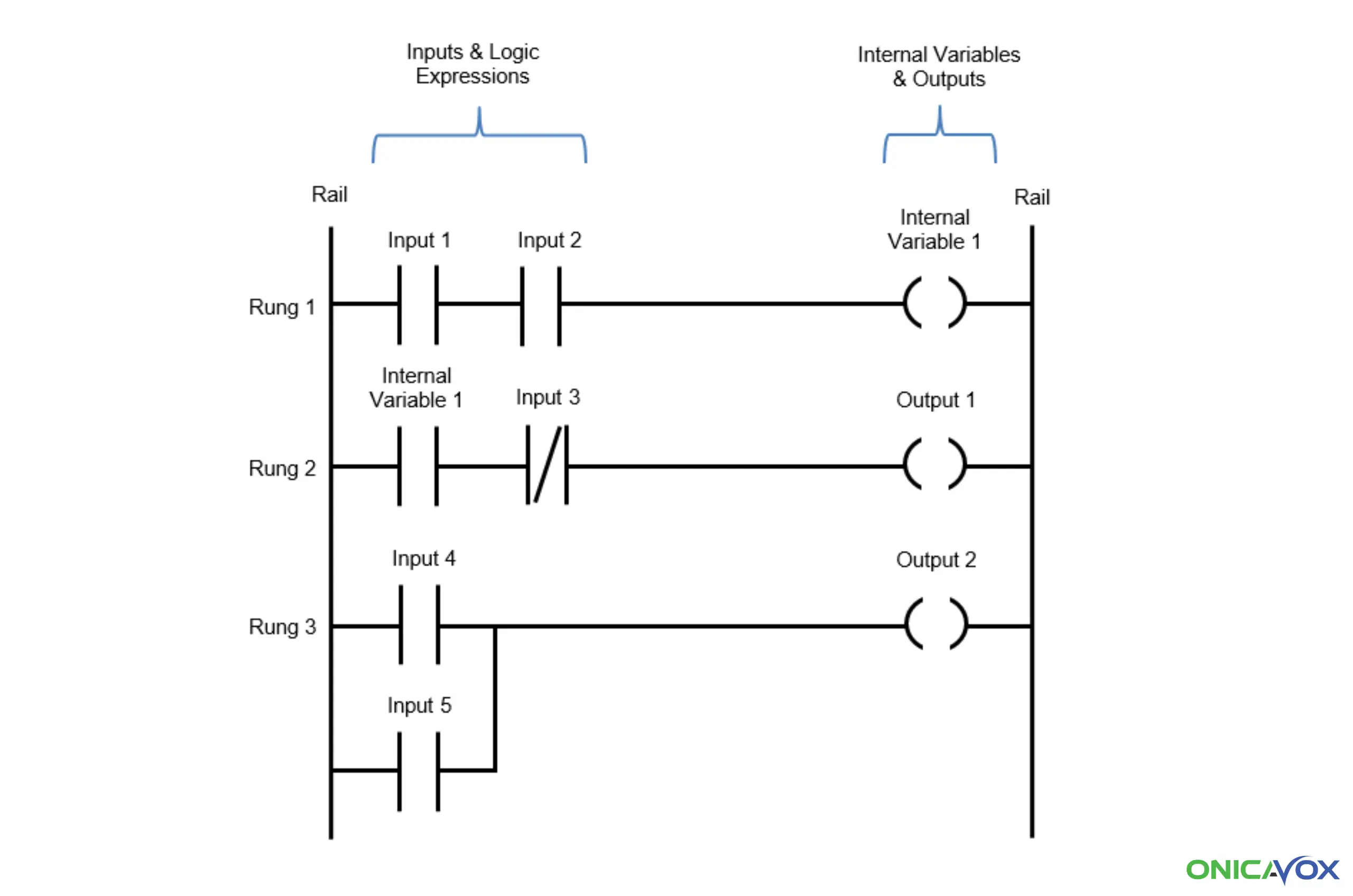
Imagine a ladder lying horizontally. Each “rung” of this virtual ladder represents a specific control function. Ladder logic diagrams are constructed using symbols and rungs, making them easy to visualize and understand.
Sequential Execution
The PLC executes each step of the ladder from top to bottom, left to right. As the software is organized in the form of a ladder, it aptly earns the name “ladder logic.”
Symbolic Language
Ladder logic instructions are expressed as conditions on both the left and right sides of the rung. The left side contains conditions (such as sensors, switches, or timers), while the right side holds trigger instructions (like actuators or outputs).
Now, let’s explore how ladder logic interacts with PLCs.
Sensors, switches, and other input devices feed information into the PLC. These devices detect physical changes (e.g., temperature, pressure, or position) and convert them into electrical signals.
Engineers create ladder logic programs to define the desired behavior of the system. Each rung represents a specific control function, such as turning on a motor or opening a valve. By combining various instructions (AND, OR, timers, counters, etc.), engineers create complex logic sequences.
Enter, the PLC …
The PLC scans the ladder logic program cyclically (at regular intervals). It evaluates each rung, checking if the conditions on the left side are met. If the conditions are true, the corresponding actions on the right side are executed (e.g., activating a relay or solenoid).
The PLC also communicates with output devices (actuators) based on the ladder logic evaluation. These devices perform actions in the real world, such as starting a motor, controlling a conveyor belt, or adjusting a valve.
Advantages of Ladder Logic
Conclusion
Ladder logic bridges the gap between control engineers and PLCs. Its visual nature, sequential execution, and symbolic language make it an essential tool for designing robust and efficient automation systems. So next time you encounter a ladder diagram, remember that it represents a powerful language driving industrial processes forward.
Here at Onicavox we strive to be at the forefront of the future of automation, empowering businesses across industries by helping them optimise their operations and maximising productivity. As a leading provider of cutting-edge automation solutions, we strive to transform the way businesses operate, enhancing efficiency, accuracy, and profitability.
Is your business ready to scale-up it's automation game? Onicavox is here to help. Please get in touch.